Arista Networks · Design Systems · 2025
Time Series Component: Research and Design
- Overview
- A new visualization component in CloudVision's design system that lets network admins read the current state and the recent history of any entity at a glance.
- Role
- Lead UX Designer · Design Systems
- Timeline
- 2026
(4 months) - Team
- 1 Designer
1 PM
1 Engineer
4 Design System Reviewers - Tools
- Figma
Impact Overview
Overnight Visibility
Operators told SEs they stopped digging through event logs each morning. The timeline view gave them what they needed on the dashboard itself.
Empty State Redesign
Customers flagged that green implied "healthy." We shipped a neutral gray based on their feedback.
Multi-Product Adoption
The component replaced the bar chart summary and is now used across CloudVision's infrastructure monitoring dashboards.
01 · Project Goal
Operators needed to see what happened while they were asleep.
Network admins needed one view that showed them what's happening now and what happened while they were away. Existing tools couldn't do both. I designed a new visualization component for CloudVision's design system that shows the current state and recent history of any device, link, or service in a single compact timeline.
"I want to view all the devices that have active events within this timerange, ignoring anything else."
02 · The Solution
Where it lives in the product.
The component had to work in two worlds: dashboards built on the newest design system patterns, and older ones still in use. Both shown here.
03 · Isolating Root Causes
Drilling into the details.
Selecting a time block that contains an alert opens a modal with more detail about what happened during that window. From there, operators can jump straight to a details page to start troubleshooting. I wanted them to go from "something's wrong" to "here's what happened" in as few clicks as possible.
04 · Customer Research
Three must-haves from operator conversations.
I checked with the design system team and eng leads that this was buildable. Research gave me three requirements I kept coming back to.
-
Must-have 01
History
"I want to be able to easily identify the state or status of this particular entity at 2:25 AM last night."
-
Must-have 02
Scalable
Networks often have thousands of devices. The component needs to handle a large number of items easily.
-
Must-have 03
Clear actions
"I want items that are important to me to stand out, and to be clear that I can interact with them for more information."
05 · What Existed Before
How events were visualized before.
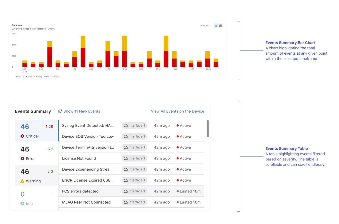
Before the Time Series Component, operators relied on a bar chart summary to see what was going on across the network. It showed event volume over time, aggregated across all devices and categories. While this gave a rough sense of when spikes occurred, it couldn't answer the questions operators actually had: which specific devices were affected, what severity level those events were, or what happened in the hours leading up to a spike.
Operators would see a spike, then manually dig through event logs to figure out what it meant. I looked at CloudVision's existing charts hoping one would fit, but single-metric line charts, bar graphs, and status tiles were too narrow for this use case. Instead, I took inspiration from outside the product: heatmaps, time graphs, and status grids in observability tools.
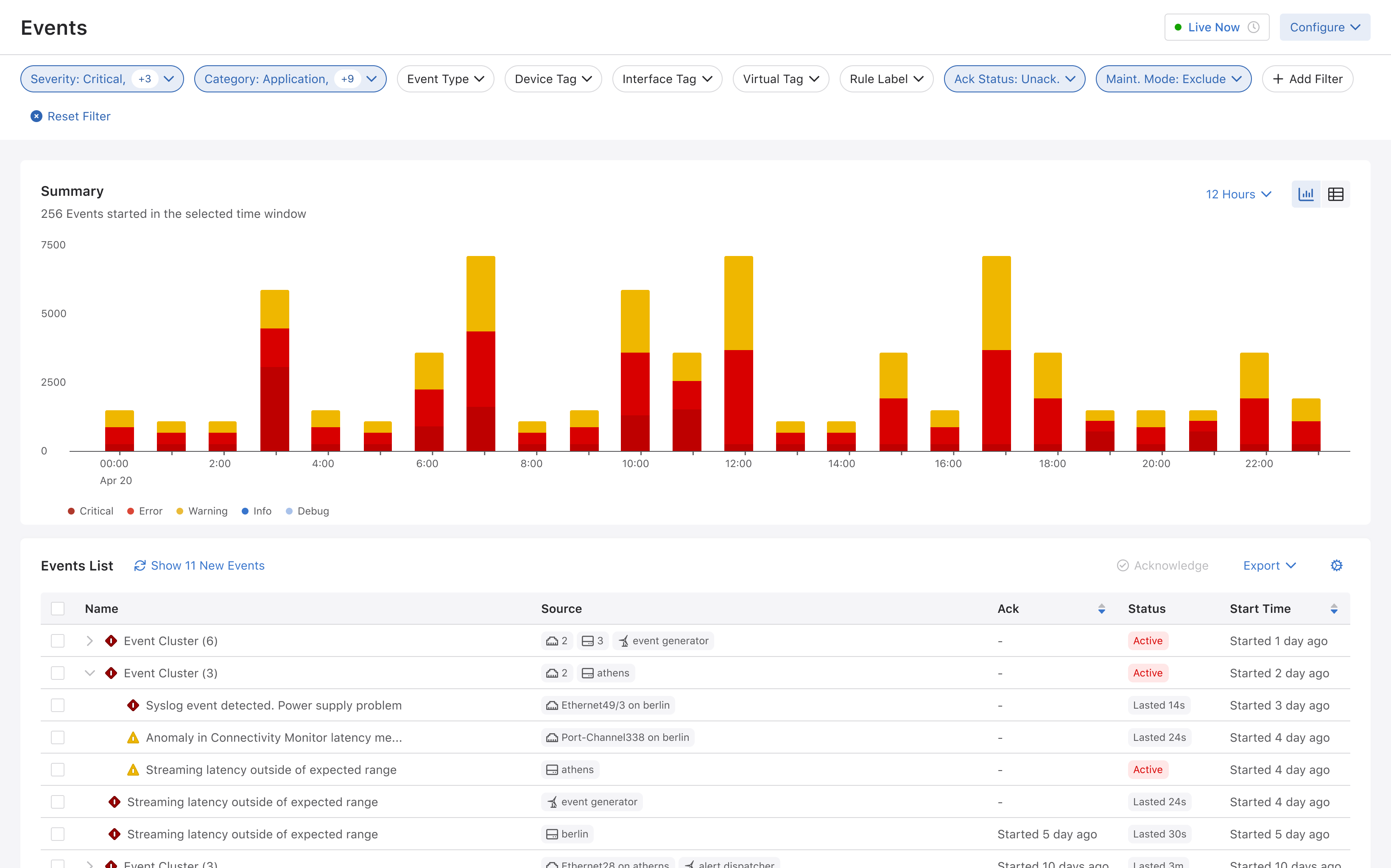
Existing Pattern Analysis
External Heatmap Research
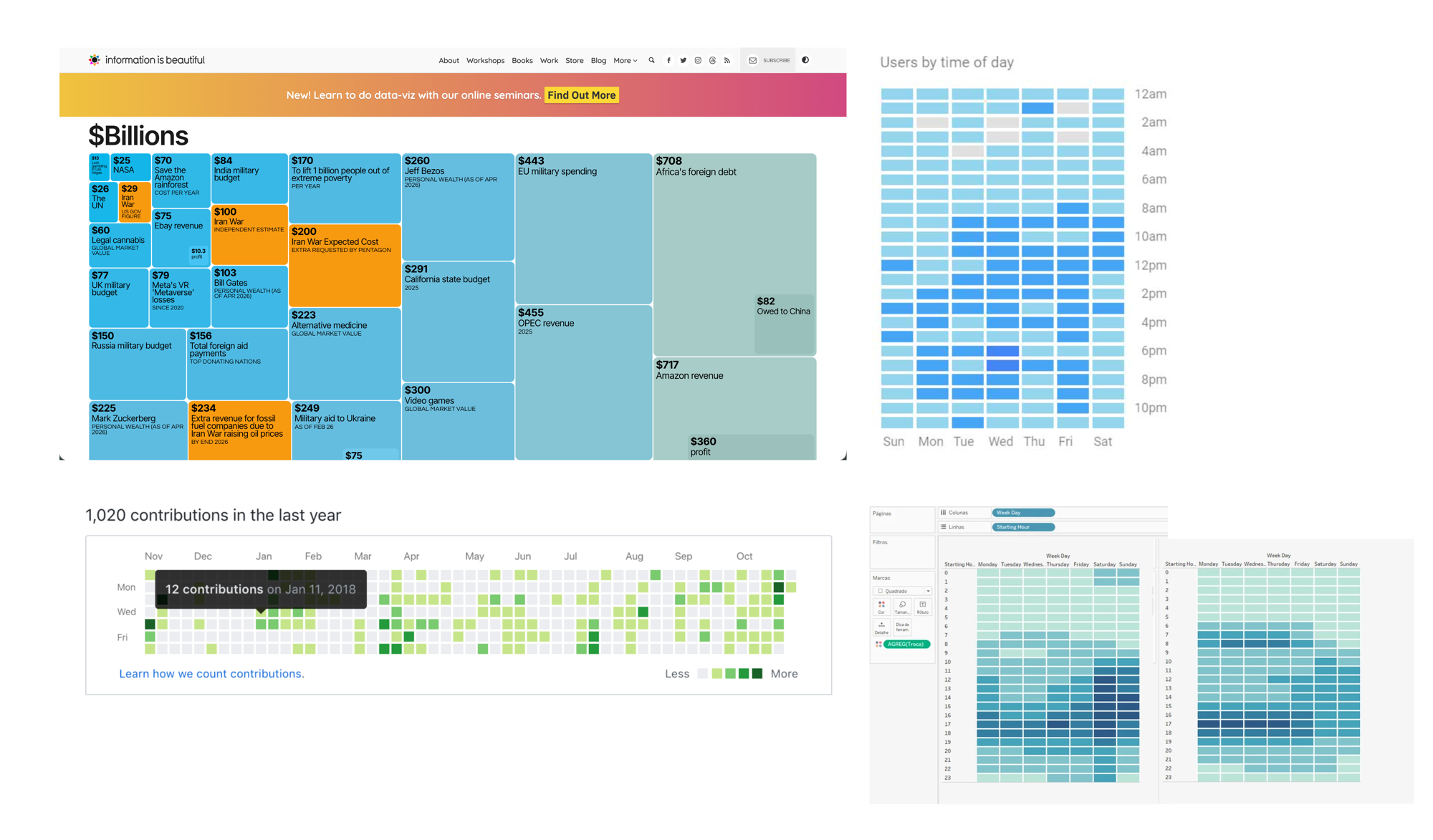
Time blocks gave me three things the bar chart couldn't:
-
Per-Device Granularity
Each row represents a single device, so operators can see exactly which entity is affected instead of reading aggregated totals.
-
Severity at a Glance
Color density encodes severity directly into the timeline. No need to hover, click, or cross-reference a legend to understand what's critical.
-
Scales Without Scrolling
The compact grid format handles thousands of entities without requiring pagination or endless scroll. More data, same footprint.
06 · Design System
How the component is built.
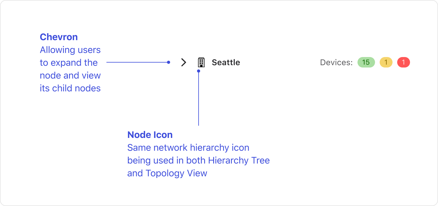
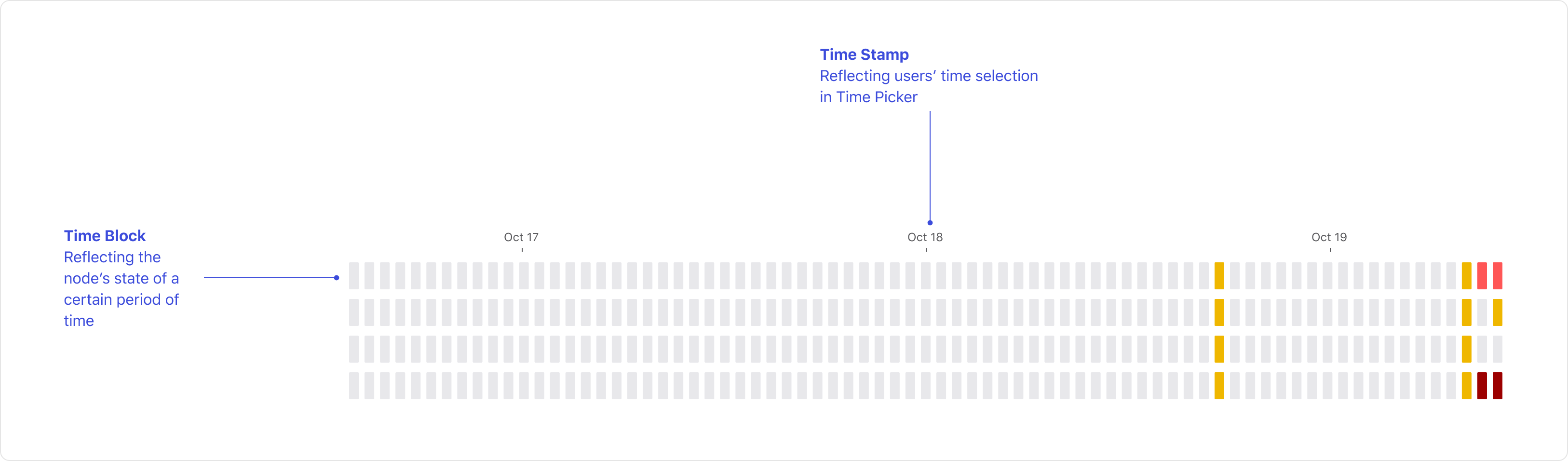
The component breaks down into three layered concerns: the overall composition (header, legend, action strip, body), the individual node row, and the timeline itself. Designing each piece with clear ownership made it easier to handle variants and states down the line.
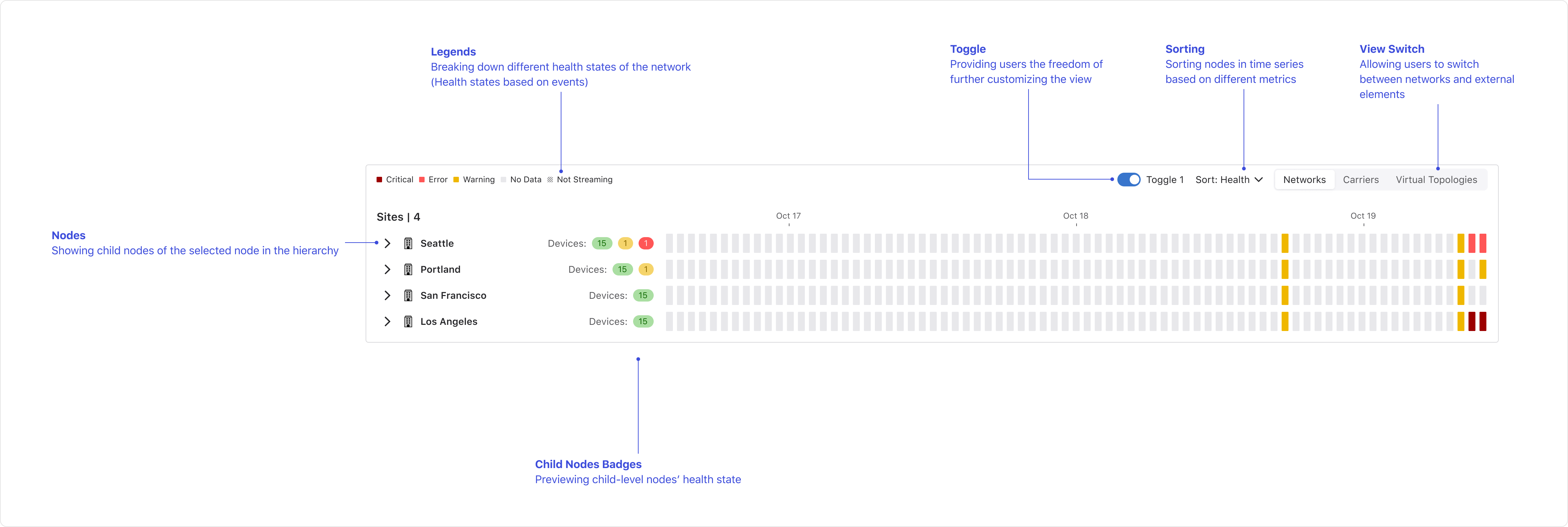
Building on the system's foundations.
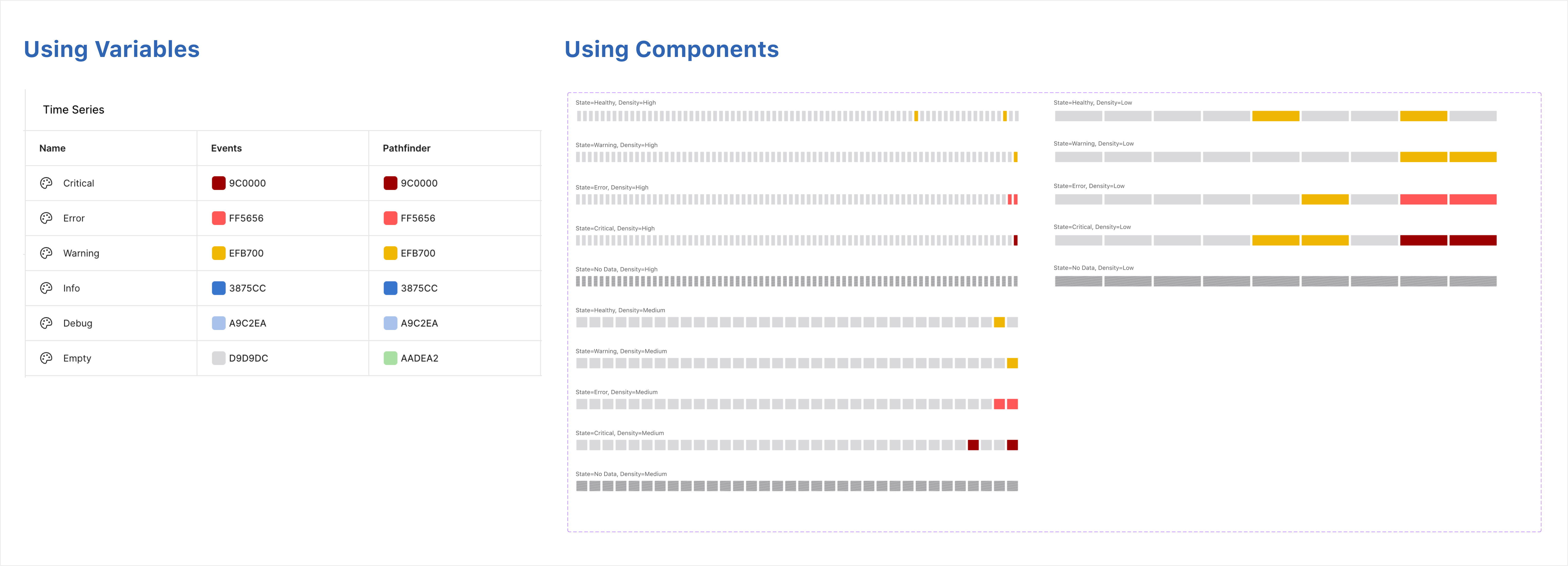
Color, spacing, and typography all reference shared variables rather than hardcoded values, so the component stays consistent with the rest of the product and adapts automatically when tokens are updated. This was especially important for the severity colors, which needed to match the same palette used across alerts, badges, and status indicators elsewhere in CloudVision.
Designing for every scenario.
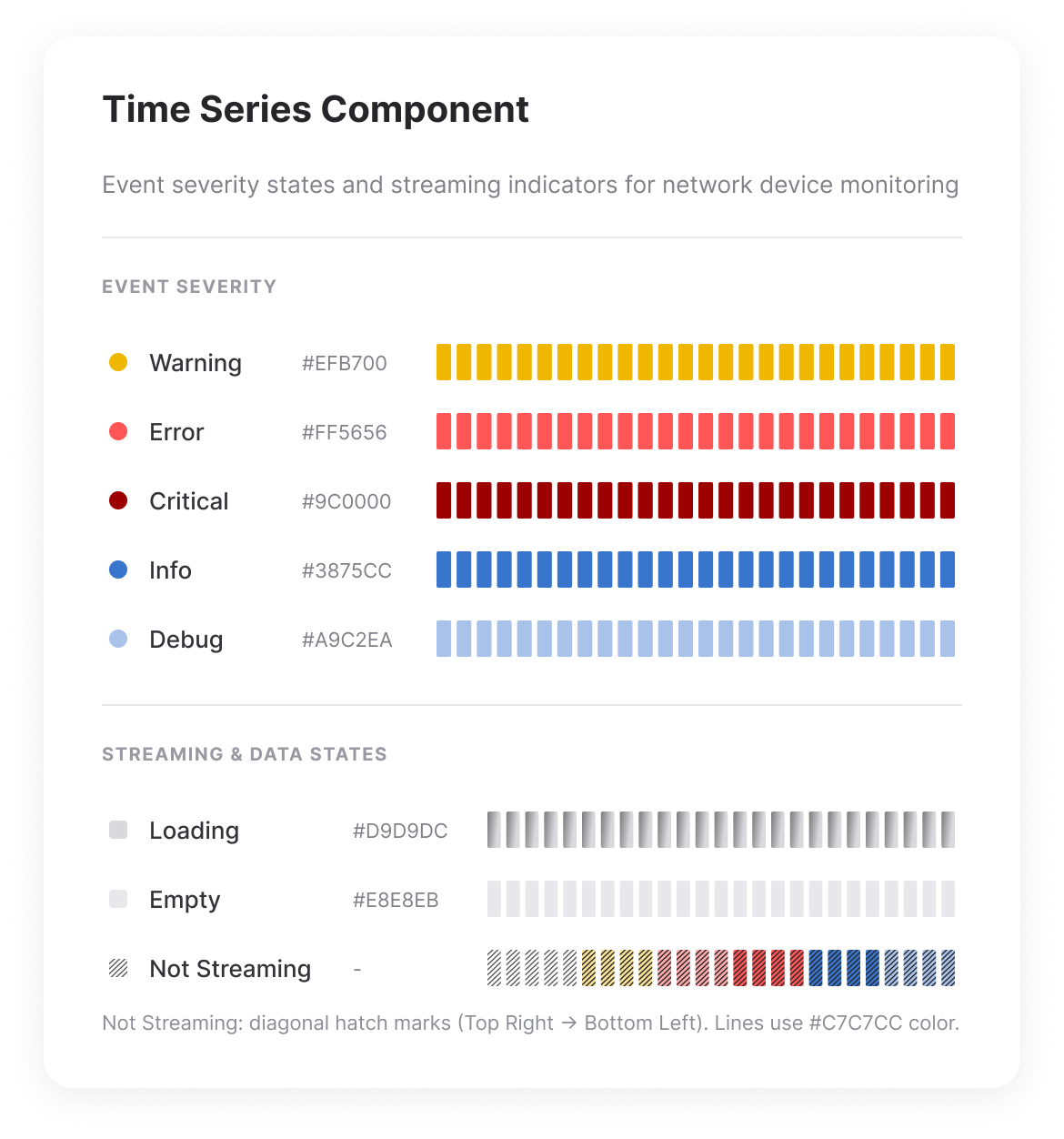
Each state carries a distinct visual treatment so operators can tell at a glance whether something is healthy, degraded, critical, or simply has no data. In a monitoring context, misreading a state can mean missing a real issue or chasing a false alarm.
07 · Iterating After Launch
Customers told us green was misleading.
Over the months that followed launch, customers told us the empty state's original colour was misleading. It suggested everything was fine even when there were no events in their selected filter. We shipped a quieter neutral tone, and the ambiguity went away.
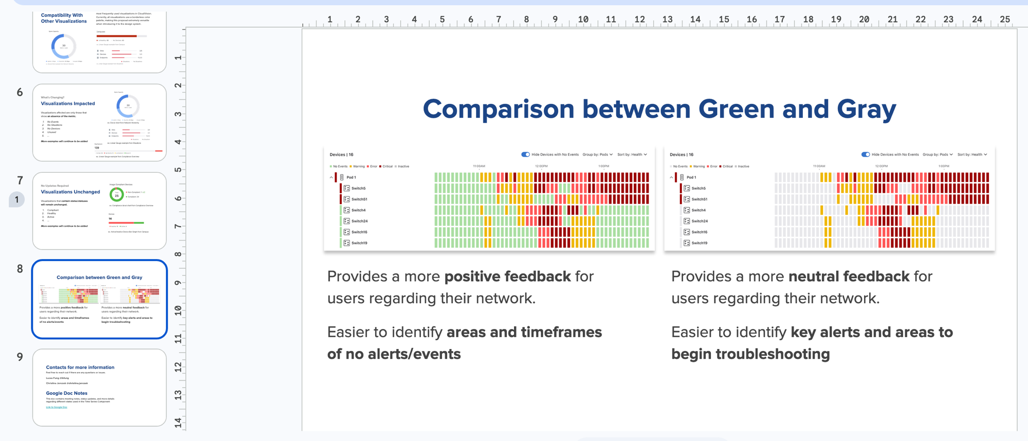
"This slide really makes it obvious for me that gray is better for this."
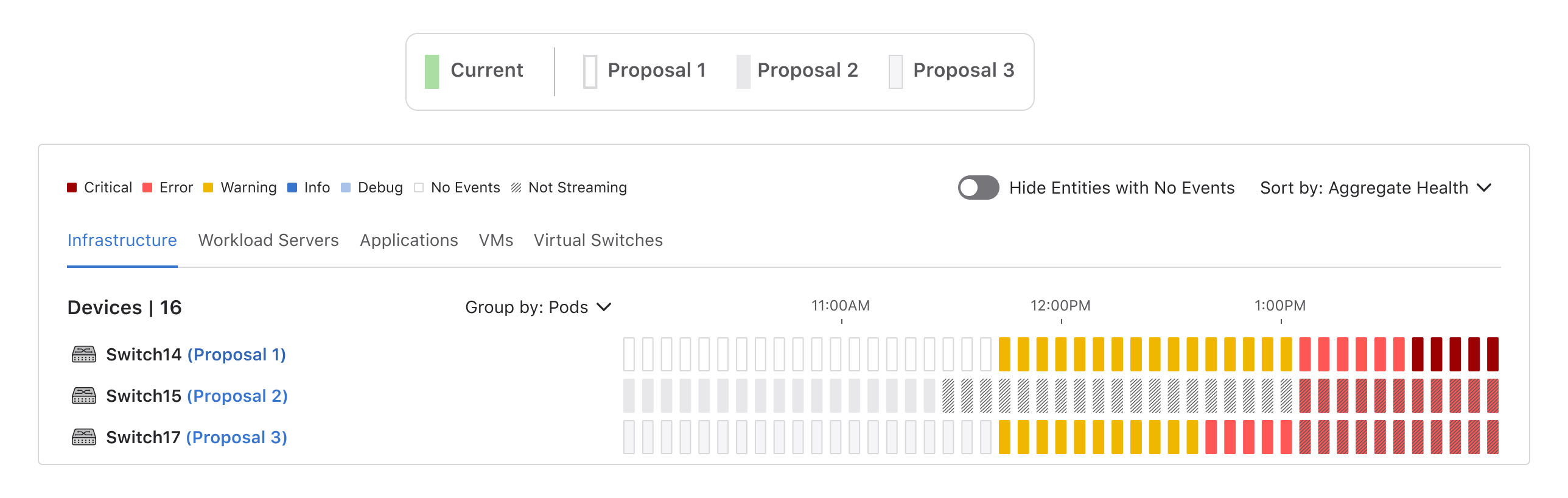
What else I tried
Before landing on gray, I explored several other color approaches for the empty and inactive states. Below shows the variations alongside the final direction that was selected.
08 · Changes Across the Design System
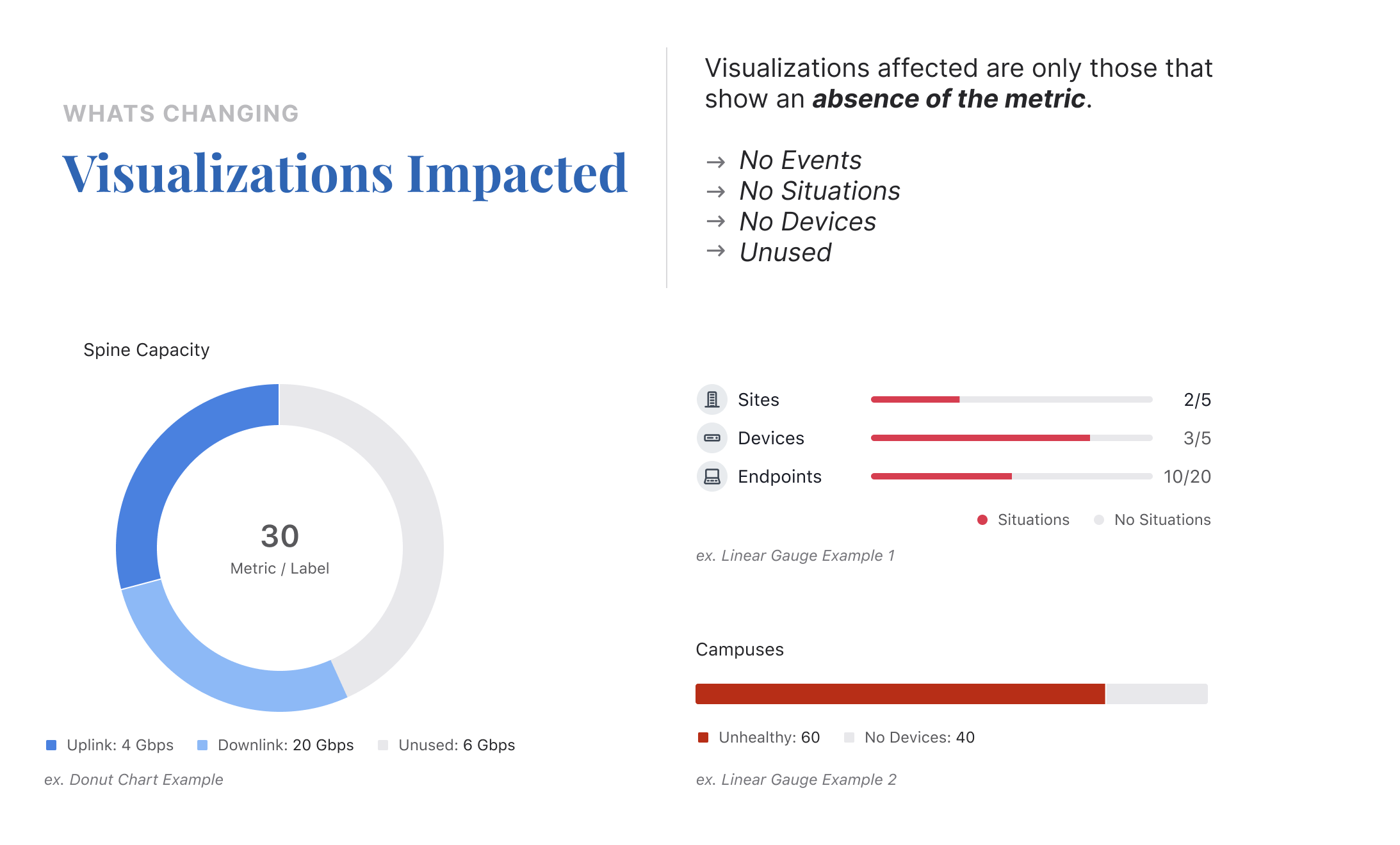
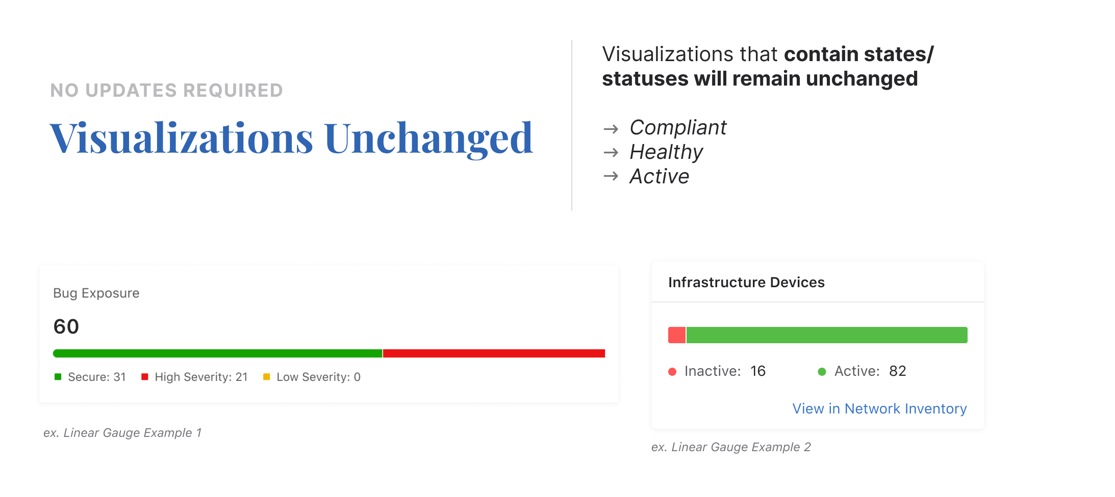
How Other Data Visualizations are Affected
It changed how we approached color in data visualization across CloudVision. If green implied "healthy" in one component, it would imply the same everywhere, and that assumption didn't hold for empty or inactive states. Below are other visualizations that adopted the same neutral treatment.
09 · Reflection
What building for a design system taught me.
This was my first time designing a component that had to work in dashboards that didn't exist yet. You can't design for a specific layout when you don't know what the layout will be. That pushed me to think in anatomy layers instead of fixed compositions, and it changed how I approach component work in general.
The green-to-gray change was humbling. I picked green thinking it was neutral. Operators read it as "everything is fine." In a monitoring tool, that's a dangerous assumption. Small color choices carry real weight when people are making decisions at 3 AM based on what they see on screen.
Next Project